INSTALLATION
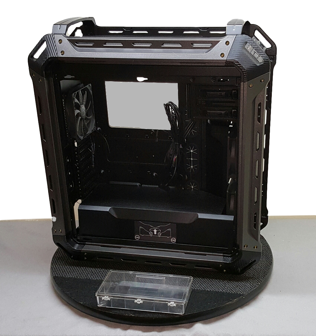
To start this build, the first thing we do is uninstall the pre-installed 120mm Cougar rear exhaust fan, as we will be replacing it with one of the red LED exhaust fans. We will wait until after the motherboard assembly is installed as that extra 25mm clearance makes placing the motherboard a tad easier.
Next we will mount the power supply. After removing the power supply cover (a bit of a challenge) we are a bit surprised to see that Cougar does not add some type of cushioning on the raised power supply supports on the bottom panel to avoid vibration/resonance/noise. No worries, we will just add some adhesive-backed thin foam rubber cushions to improve vibration isolation. These can be obtained at a craft supply store such as Michael’s or JoAnn Fabric. Using a non-modular power supply adds just a bit more challenge to cable management, but a full tower case has extra room and clearance. Should not be any significant issues with tucking away unused cabling.
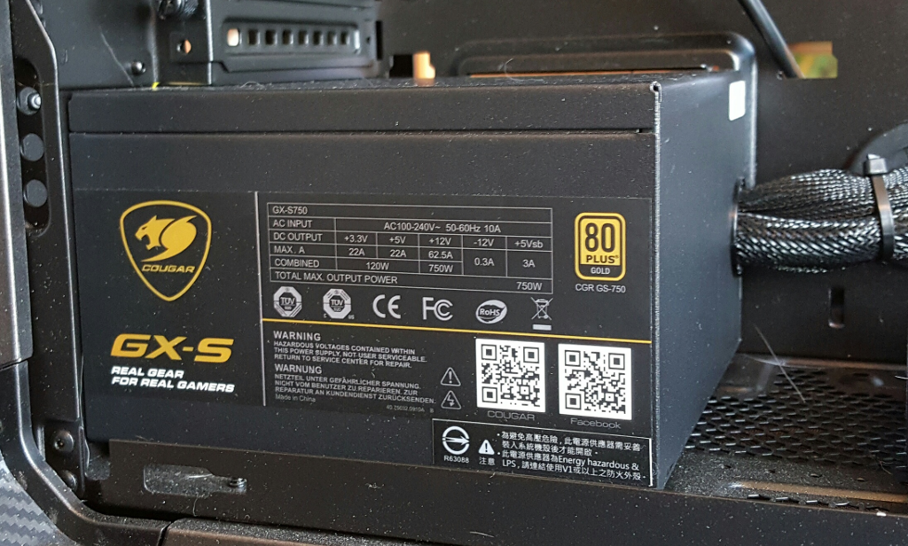
Here we see the power supply is now screwed into place. Cougar supplies chrome screws with the power supply, and black screws with the Panzer Max. We have utilized the black screws to match the case exterior. We have pre-routed the 24-pin main power cable, the CPU 8-pin power cable, and one of the 2 SATA power cables close to where they will be needed before installing the motherboard. The SATA power cable will be used at a minimum for the optical drive that we will mount in the upper 5.25” bay. We will not be utilizing either of the 2 x PCI-e power cables, so we will go ahead and (semi)-permanently bundle these together and out of the way in the cable management channel at the bottom of the case behind the motherboard tray. Front panel headers, USB headers and fan controller leads are all temporarily secured at the front of the chassis until we are ready for them.
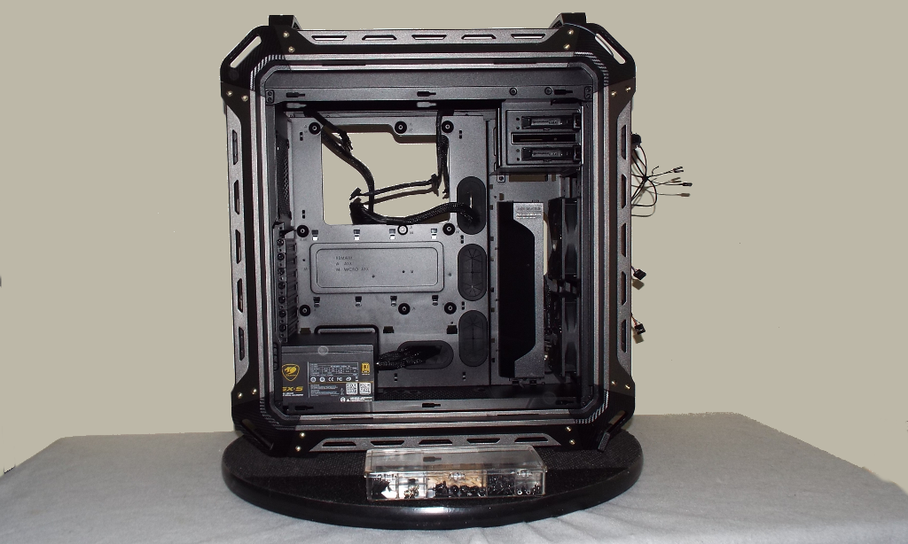 The remaining SATA power cable and the single Molex power cable we will coil temporarily out of the way in the area where the 4 x .2.5” drive sleds reside at the right front of the case. We have removed these as we will be utilizing an NVMe PCIe SSD for our operating system drive, and our storage drive (SSD) will be mounted in one of the two trays on the backside of the motherboard. Removing the unused drive trays will also create a nice chunk of additional space to help simplify cable management. We have also removed the Panzer Max’s air diverter that sends air into this area since it will not be required.
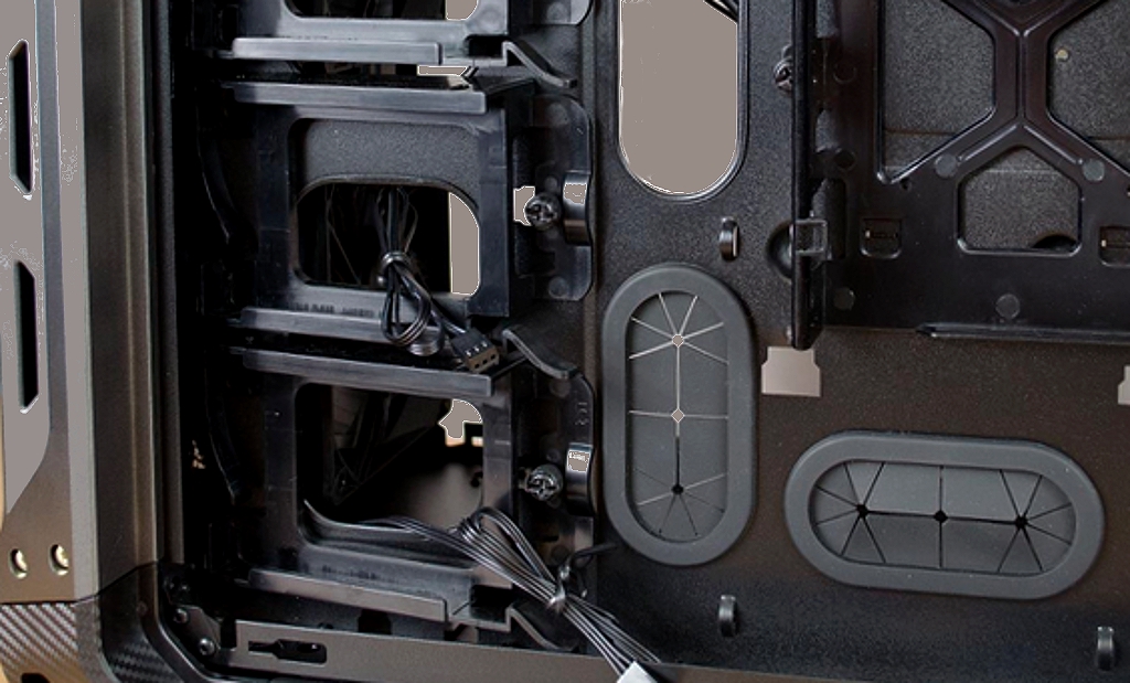 2.5″ drive trays (left) before removal
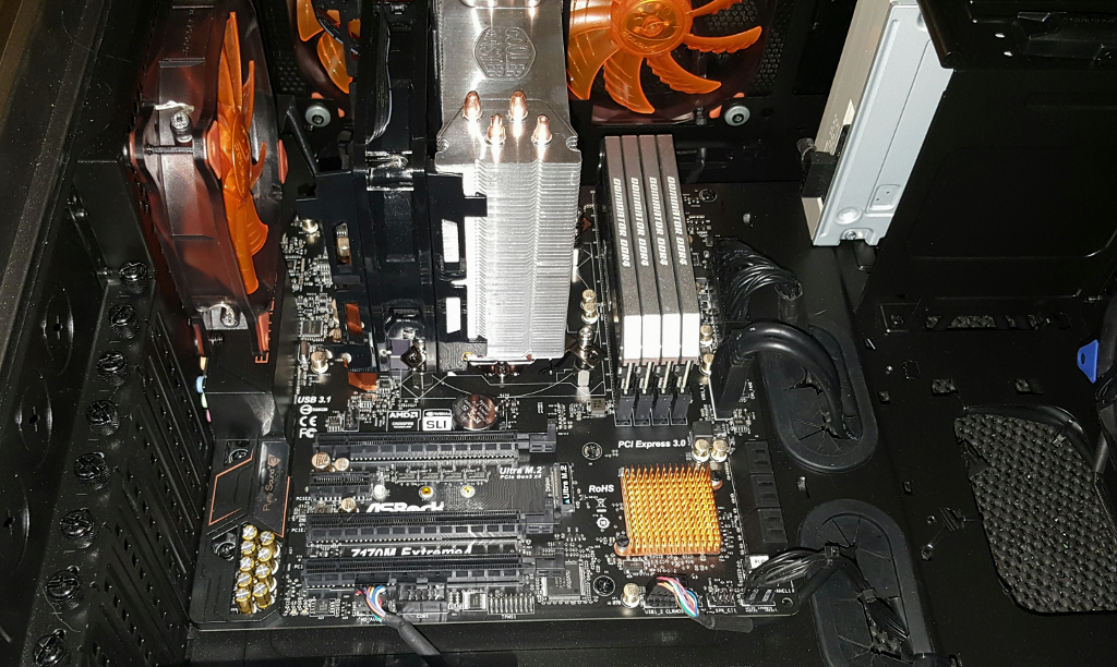
Next we will install the motherboard. Before installing it, we will go ahead and install the memory modules, as well as the CPU and CPU cooler. To facilitate installing the motherboard “assembly”, we will lay the Panzer on its right side. The next image is of the motherboard assembly screwed into place, and we have also connected the CPU power, main 24-pin power, USB 3.0, USB 2.0, and front panel header cables.