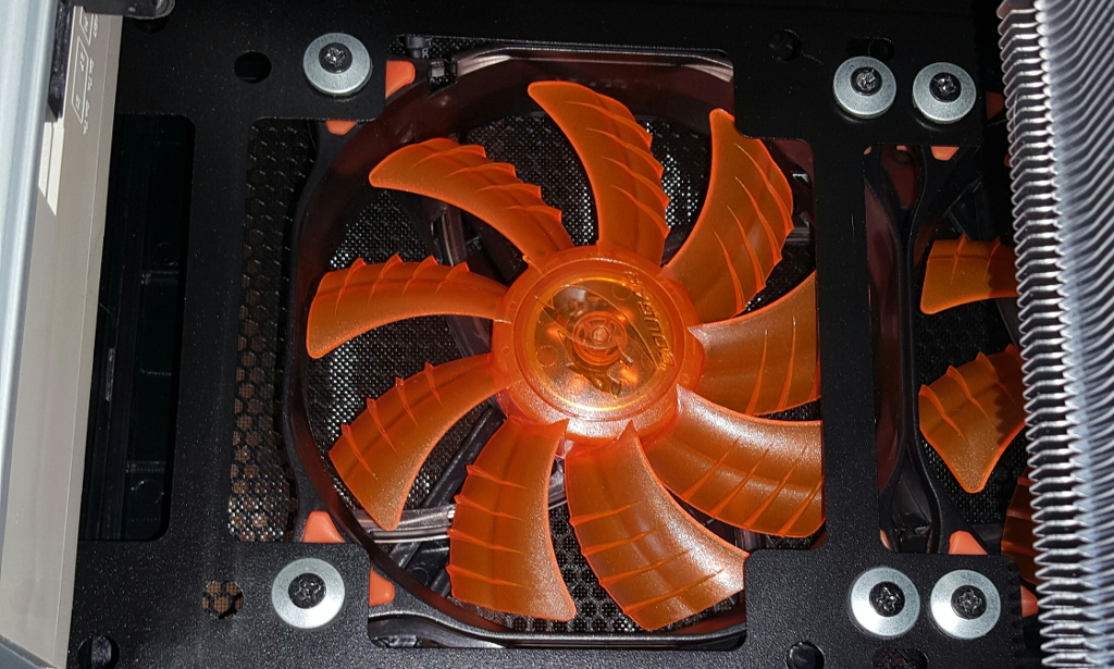
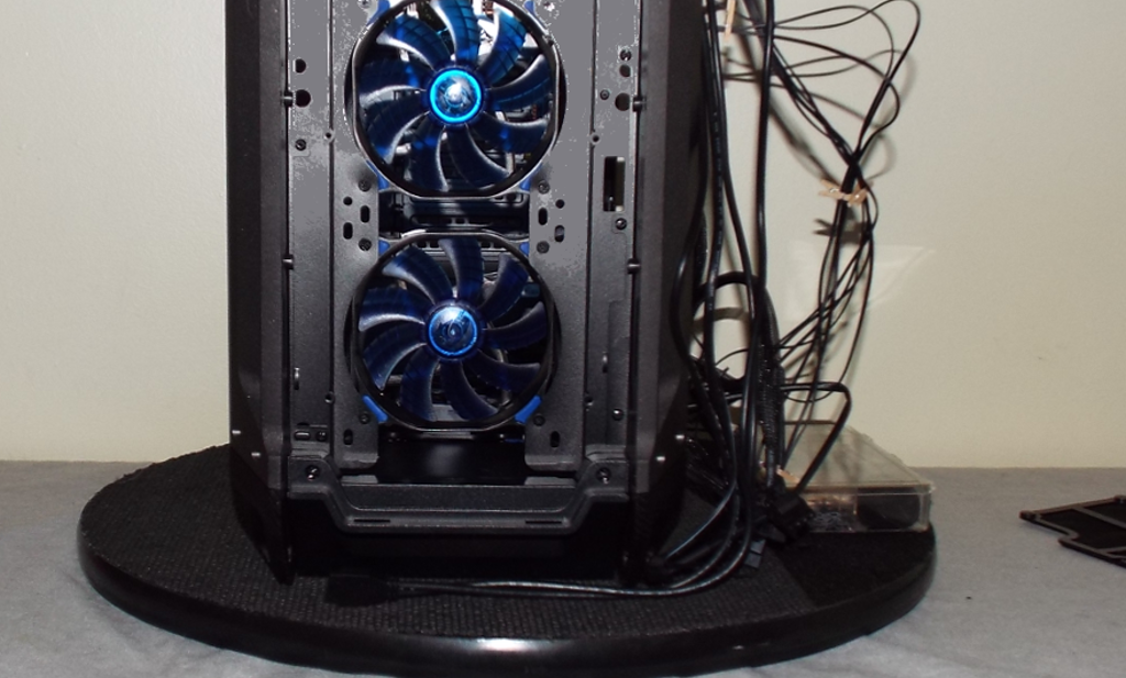
Next we install our case fans. Cougar has supplied us with 3 x red and 3 x blue of their CFD120 LED case fans with hydraulic bearings. First we will uninstall the 2 x 120mm pre-installed Cougar fans from the front panel area. In order to keep things “logical”, we will install the 3 x blue LED fans as intake (two in the front panel and one in the bottom) and a pair of the red LED fans in the top panel as exhaust, as well as a single red LED 120mm fan in the rear panel. As you can see in the previous image, we have installed the red fans into the top panel prior to securing the motherboard in place, as access to the mounting screws for these fans is rather limited otherwise. The Panzer Max comes with a pre-installed fan controller, and comes supplied with a pair of 1 x 3 fan cable splitters. We will wire all three of the intake fans to one, and all three of the exhaust fans to the other so that all three of either intake or exhaust are controlled in unison.
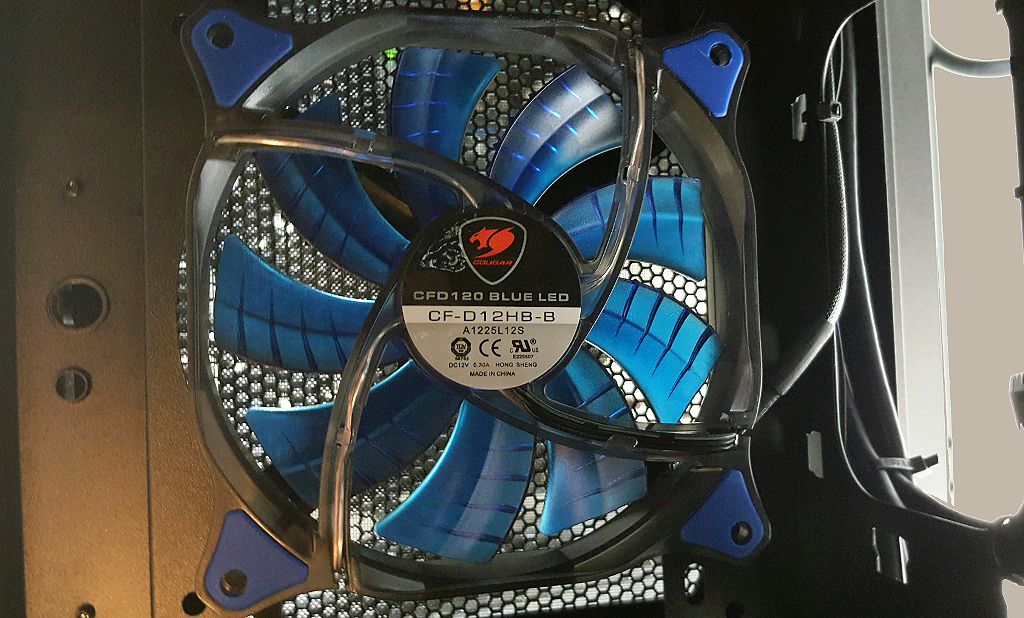
Getting to the front fans requires removing the front panel. This is accomplished by a sharp tug on a recess on the bottom edge of the front panel to pull it loose, thus exposing the front fan area. Once inside the fan area, we can now readily uninstall the Panzer Max’s pre-installed pair of 120mm front fans, and replace them with the blue Cougar CFD120 LED fans. We will now also install the third blue Cougar CFD120 LED fan on the bottom of the chassis, well clear of the power supply.
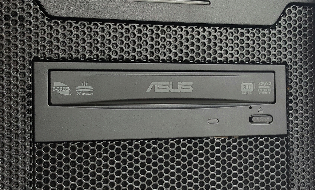
Next we will mount the optical drive in the upper 5.25” bay. Even with securing the optical drive into place with screws, as opposed to relying only on the tool-less latching mechanism, the optical drive is installed in only a couple of minutes.
Now is likely a good time to tidy up some of our wiring, especially on the backside of the motherboard tray. Even when building in a full tower case, there is still a finite amount of space for cable management, and condensing and bundling of wires is the name of the game in achieving a tidy build. Organizing the cabling also improves air flow on that side of the motherboard, in an already narrow and crowded space. When we connect up the splitters for the fan control to all six of our case fans, we now have quite a variety of cables that can be tidied up to improve not only appearance, but also air flow. This image shows the case fan and splitter wiring before we connect and organize it all.
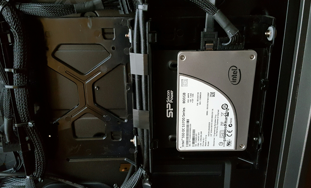
Now we can install both of our storage devices. We will install our storage SSD in one of the 3.5″ drive trays on the backside of the motherboard tray, utilizing a 3.5″ to 2.5″ adapter we have on hand from another SSD kit. We will connect the SATA power connection, leaving the SATA data cable to be installed later, along with the SATA data cable for the optical drive. We will connect these after the operating system is installed, to avoid any possible complications during that process. Here we see our Intel SSD DC S3700 800GB installed on the backside of the motherboard tray.
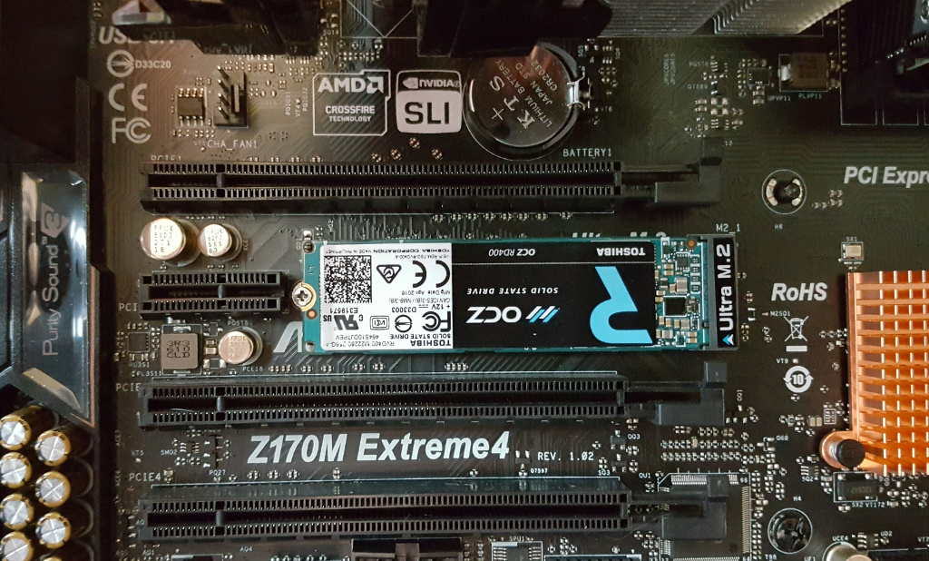
The OCZ RD400 PCIe NVMe operating system SSD is next to install. It comes mounted to an adapter card for a PCIe slot, but we will be removing it from the adapter card and installing it directly into the motherboard’s Ultra M.2 slot. This slot operates at PCIe Gen3 x4, which matches the rating of the RD400. Here we see it installed into the Ultra M.2 slot.
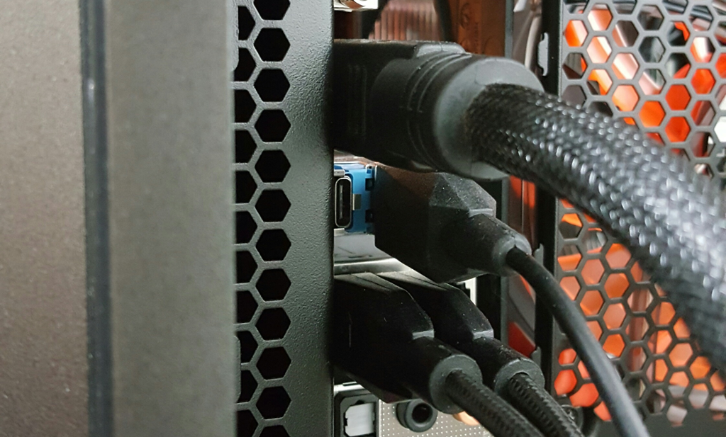
Next to connect are our Cougar Attack X3 keyboard and Revenger mouse to a pair of rear-panel USB ports (actually three ports – the keyboard has two separate USB cables – one for power and one for functions). The HDMI cable for the monitor gets connected now also. We will now double check all of our wiring and connections to prepare for installing our operating system.